Table of Contents
Guardian & Guardian Wave Installation Guide
Installation guide for Guardian and Guardian Wave APS systems using Signal Power Interface (SPI) in pedestrian signal heads, connecting via four-conductor cable to eliminate traffic cabinet equipment needs.


Guardian | Guardian Wave |
 |  |
Overview
This guide provides installation information for the Guardian and Guardian Wave Accessible Pedestrian Signal (APS) systems.
The Guardian APS system operates independently from the traffic cabinet by using a Signal Power Interface (SPI) installed inside the pedestrian signal head. The SPI provides power and signal communication to the Guardian push button station using a four-conductor cable.
This design eliminates the need for APS equipment inside the traffic cabinet and allows installation using existing pedestrian signal wiring.
System Components
A typical Guardian APS installation includes the following components:
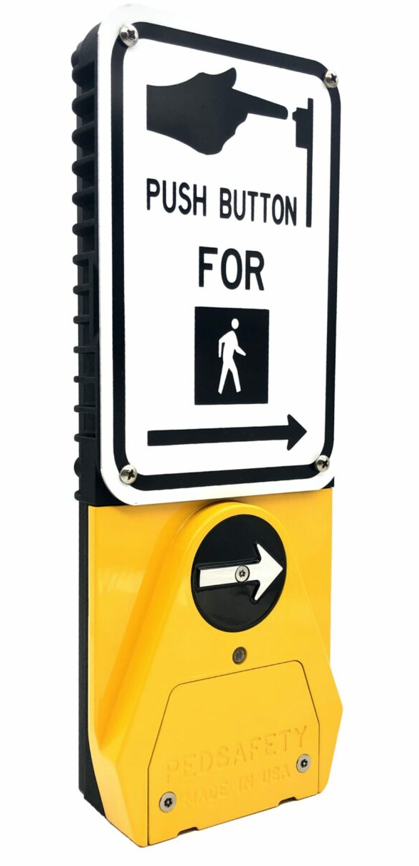
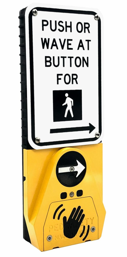
• Guardian or Guardian Wave APS station
• Signal Power Interface (SPI)
• Four-conductor cable between SPI and APS station
• Pedestrian sign and mounting hardware
Installation Requirements
Before installation, verify the following:
• Pedestrian signal head has space for the Signal Power Interface (SPI)
• Existing wiring between the signal head and push button station is suitable for reuse
• Mounting location complies with MUTCD and ADA accessibility guidelines
• Push button station height and placement meet local accessibility requirements
Signal Power Interface Installation
The Signal Power Interface (SPI) is installed inside the pedestrian signal head.
Installation steps:
- Disconnect power to the pedestrian signal circuit.
- Open the pedestrian signal head housing.
- Install the SPI module according to the wiring diagram.
- Connect the WALK and DON’T WALK signal wires to the SPI.
- Connect the four-conductor cable that runs to the Guardian APS station.
- Secure the SPI inside the signal head.
APS Station Mounting
Install the Guardian or Guardian Wave station at the pedestrian push button location.
Installation steps:
- Remove any existing pedestrian push button equipment.
- Position the Guardian APS station on the mounting pole.
- Route the four-conductor cable into the station housing.
- Secure the station using the appropriate mounting hardware.
- Ensure the tactile arrow is aligned with the direction of travel.
Station Wiring
Connect the field wiring between the SPI and the APS station.
Typical wiring includes:
• Power and communication from the SPI to the APS station
• Four-conductor cable between the signal head and station
Verify correct wiring before restoring power to the system.
System Verification
After installation is complete:
- Restore power to the pedestrian signal circuit.
- Verify the locator tone is active.
- Press the push button to place a pedestrian call.
- Confirm audible walk indication during the WALK phase.
- Verify vibrotactile arrow operation.
- Confirm correct operation of extended button press features.
For Guardian Wave stations, also verify hand-wave detection activates a pedestrian call.
Downloads
Was this helpful?
Guardian Duo Wiring Guide