Table of Contents
Wiring Guide - Radar Speed Signs
Radar Speed Signs: Region-specific solar/AC power kits with safety-first installation for optimal traffic monitoring.


There is a -M at the end of the model number for MUTCD compliant rings
Solar Kit Options
Radar Speed Signs can be equipped with different solar or AC power kits based on regional sunlight exposure:
- Solar South Kit: 60 Watt / 35Ah (M75-SOLAR-000S)
- Enhanced Solar South Kit: 60 Watt / 70Ah (M75-SLR70-000S)
- Solar Central Kit: 100 Watt / 70Ah (M75-SOLAR-000C)
- Enhanced Solar Central Kit: 100 Watt / 140Ah (M75-SLR14-000C)
- Solar North Kit: 150 Watt / 140Ah (M75-SOLAR-000N)
AC Power Kits
- Standard AC Power Kit: 60 Watt (M75-ACPWR-U060)
- Enhanced AC Power Kit: 200 Watt (M75-ACPWR-U200)
Wiring Instructions
Follow these steps to ensure a safe and efficient installation, adhering to the best practices prescribed by the NEC. Only qualified technicians should perform these installations.
Power Supply Connection
The iQ Series Radar Speed Sign may come with a TraffiCalm power supply that can be solar or AC line powered, typically ending in a DC Barrel connector (2.5mm x 5mm). If the sign is not provided with a TraffiCalm power supply, it will likely have 18 to 14 AWG insulated wires. Use at least 18 AWG wire for connections up to 6 feet; for longer distances, adjust the wire gauge accordingly to handle a 3 Amp load with less than ¼ volt drop over the length of the wire.
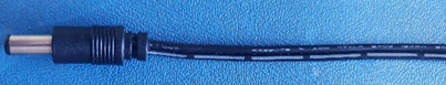
*DC Barrell connector 2.5mm
Connecting the Sign to Power
- Safety First: Ensure all power sources (battery, solar, or AC) are disconnected before starting.
- Conduit Installation: Use a liquid-tight conduit to run from the power supply to the sign's field wiring plate, entering through one of the designated knockouts.
- Wiring Route: Through the conduit, run the 12VDC Positive, common, and Earth/chassis ground wires from the power supply to the sign.
- Ground Connection: Attach the Earth ground using a ring lug (not provided) to the stud on the field wiring plate.
- Refer to Wiring Diagrams: Consult the attached wiring diagrams for proper routing of wires to the respective components.
- Power Reconnection: Reconnect the power source—battery, line power, or solar panel.
- Testing: Once reconnected, test the sign to verify successful installation.
DC Connection
- DC Connection: If using a barrel connector, you can plug it into the mated female barrel connector or cut the connector off, separate the wires, and strip ½ inch of insulation from each. Identify the positive wire by the white stripe.
- Terminal Connections:
- Connect the positive wire (white stripe to the terminal marked “+12VDC.”
- Connect the common wire to the terminal marked “DC COM.”
- Reassemble: Secure the field wiring plate back onto the sign.
NOTE: The M75-15DFB-xxxx models only have the barrel connection option to connect the DC power
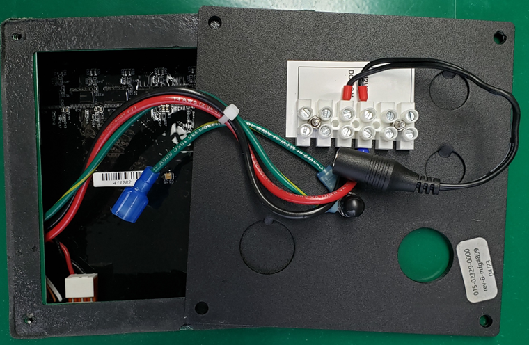
*iQ1500 power panel
Wiring Diagrams
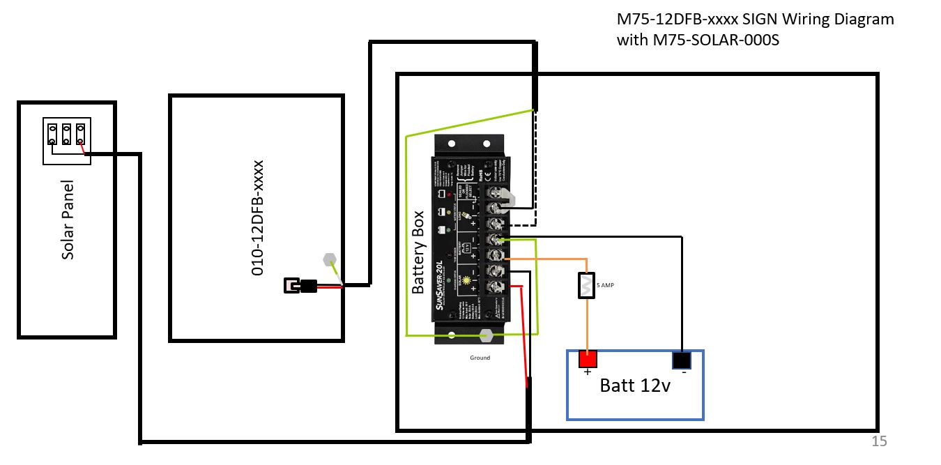
South
- Solar South Kit (M75-SOLAR-000S)
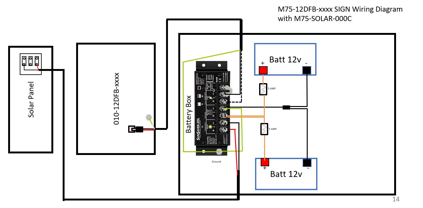
Central
- Solar Central Kit (M75-SLR70-000C)
- Enhanced Solar Central Kit (M75-SOLAR-000C)
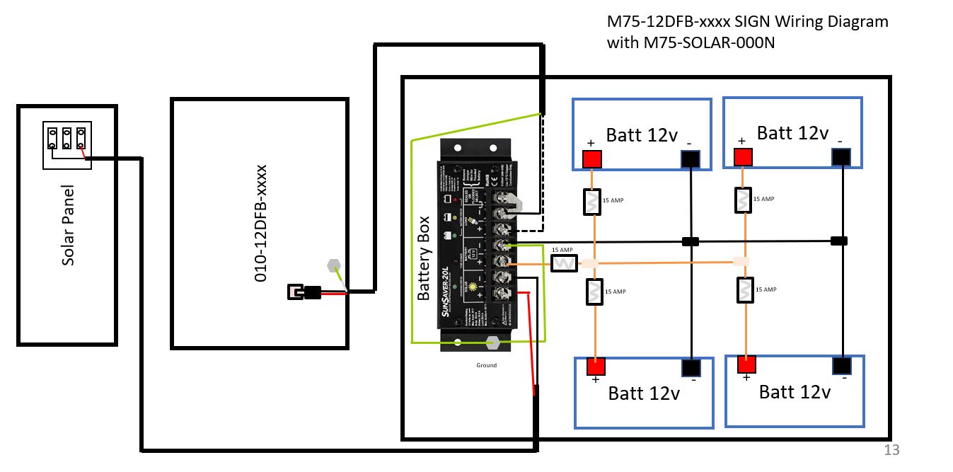
North
- Solar North Kit (M75-SLR14-000N)
- Enhanced Solar North Kit (M75-SOLAR-000N)
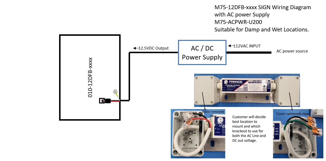
A/C
- Standard AC Power Kit: 60 Watt (M75-ACPWR-U060)
- Enhanced AC Power Kit: 200 Watt (M75-ACPWR-U200)
Conclusion
Was this helpful?
Wiring Guide - Radar Speed Signs with External Beacons