Table of Contents
Wiring Guide - Radar Speed Signs with External Beacons
Expert wiring guide for TraffiCalm Radar Speed Sign beacons: precise connections for enhanced road safety monitoring

Updated
by Dylan Solberg
Wiring Guide for Radar Speed Signs with External Beacon Connections

MUTCD Sign Rings: If your controller is running firmware 401N or >, adjust brightness from 100% to 60%. Failure to do so will result in higher power draw and solar systems may fail.
Is my ring MUTCD?
There is a -M at the end of the model number for MUTCD compliant rings
There is a -M at the end of the model number for MUTCD compliant rings
Introduction: TraffiCalm Radar Speed Signs provide an option to connect external beacons, enhancing visibility and driver feedback. This guide will help you correctly wire the external beacons using the provisions available on the radar speed sign.
Tools and Materials Needed
- Screwdriver
- Wire strippers
- Multimeter
- Suitable cabling
- Optional: Insulation tape or heat shrink tubing for secure connections
External Beacon Connection Overview
The connection for external beacons is made via a six-pin connector located under the access panel at the bottom of the Electronic Control System (ECS). This panel must be handled carefully to avoid damage to the interior components.
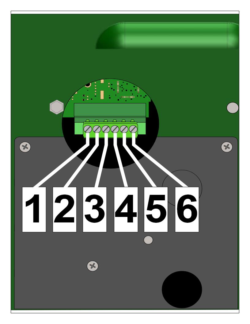
Connector Pin Assignments and Wiring Setup
- Access the Connector: Open the access panel on the ECS to reveal the six-pin connector.
- Pin Configuration:
- Pin 1: Fused (1A) 12VDC output from the Display DC input
- Pin 2: Opto-Isolator Positive common
- Pin 3: Beacon DC control #1 (activates DC Return when active)
- Pin 4: Beacon DC control #2 (activates DC Return when active)
- Pin 5: Beacon Output DC COMMON (Fused at 1A)
- Pin 6: Display Common
Wiring the Beacon
- For isolated operation, connect the beacon power to Pin 2 (+) and common to Pin 5 (-).
- If no isolation is needed, create jumpers between Pin 1 and Pin 2 and between Pin 5 and Pin 6 to draw power directly from the display batteries.
- Connect the beacon's positive wire to the appropriate power source and the beacon's negative wire to either Pin 3 or Pin 4, depending on which output is used.
Wiring Diagrams
Basic Wiring Configuration
Wiring Beacons with Relays
Wiring External Flasher Timing
Configuring Beacon Behavior
- Default Control Mode:
- Output #1 (Pin 3) activates when vehicle speed exceeds the set speed limit.
- Output #2 (Pin 4) activates when the display is in RADAR mode.
- Programmable Modes (using DFB software):
- Beacon Mode 1: Beacons alternate at a 1 Hz rate when the sign is active in radar mode.
- Beacon Mode 2: Beacons alternate at a 1 Hz rate when the vehicle speed exceeds a selected threshold.
Testing and Troubleshooting
- Test Connections: After wiring, use a multimeter to verify the correct voltage at the beacon connections.
- Check Operation: Power on the sign and observe the beacon's response to ensure it functions as programmed.
- Troubleshoot Issues: If beacons do not operate as expected, recheck wiring connections for any loose or incorrect contacts, and ensure programming settings are accurately applied.
Conclusion: By carefully following these wiring instructions, you can successfully integrate external beacons with your TraffiCalm Radar Speed Sign. Regular maintenance checks and proper setup ensure the system delivers effective speed monitoring and enhances road safety. For more detailed information or troubleshooting, refer to the detailed user manual or contact technical support.
Was this helpful?
Wiring Guide - Radar Speed Signs