Table of Contents
- Wiring Overview and Installation Guide
- Overview
- System Architecture
- Typical Wiring Configuration
- Wiring Components
- Cabinet to Signal Head
- Signal Power Interface to ABD
- Audible Beacon Device Terminal Connections
- Signal Power Interface (SPI)
- Mounting Location
- Installation Best Practices
- Commissioning Procedure
- Installation Checklist
- Operating Environment
Audible Beacon Device (ABD) Wiring Overview and Installation Guide
Audible Beacon Device installation guide covering wiring overview, system architecture, mounting location, terminal connections, installation best practices, and commissioning procedures for pedestrian crossing safety.

- Wiring Overview and Installation Guide
- Overview
- System Architecture
- Typical Wiring Configuration
- Wiring Components
- Cabinet to Signal Head
- Signal Power Interface to ABD
- Audible Beacon Device Terminal Connections
- Signal Power Interface (SPI)
- Mounting Location
- Installation Best Practices
- Commissioning Procedure
- Installation Checklist
- Operating Environment
Wiring Overview and Installation Guide

906-0021-Audible-Beacon-Device-Wiring-Quick-Guide-Rev-F.pdf
 |  |
Overview
The Audible Beacon Device (ABD) provides audible guidance to pedestrians during crossing phases. The device emits locator tones and audible messages to help pedestrians identify the destination end of the crosswalk and confirm safe crossing intervals.
The ABD is typically installed near the pedestrian signal head and connected to a Signal Power Interface (SPI) located inside the signal housing. The SPI converts pedestrian signal indications into control signals used by the ABD.
This guide outlines the standard installation practices, wiring connections, and commissioning steps for the Audible Beacon Device.
System Architecture
A typical Audible Beacon Device installation consists of the following components:
- Traffic control cabinet
- Pedestrian signal head
- Signal Power Interface (SPI)
- Audible Beacon Device (ABD)
- Pedestrian push button or APS station
- Field wiring between the cabinet and the signal equipment
The Signal Power Interface acts as the electrical interface between the pedestrian signal indications and the ABD.
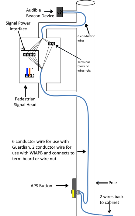
Typical Wiring Configuration
The Audible Beacon Device connects to the Signal Power Interface located inside the pedestrian signal head.
Typical wiring includes:
- Field wiring from the traffic cabinet to the pedestrian signal head
- Internal wiring from the Signal Power Interface to the Audible Beacon Device
The diagram below illustrates a typical installation configuration.
Wiring Components
A standard ABD installation uses the following wiring paths.
Cabinet to Signal Head
A multi-conductor field cable connects the traffic control cabinet to the pedestrian signal head. This wiring provides the pedestrian signal indications used to trigger the audible beacon.
Typical installations use 6-conductor field wiring between the cabinet and signal assembly.
Signal Power Interface to ABD
A 4-conductor cable connects the Signal Power Interface to the Audible Beacon Device.
This cable carries:
- Power
- Ground
- Walk signal
- Don't Walk signal
These connections allow the ABD to activate audible cues during the pedestrian phase.
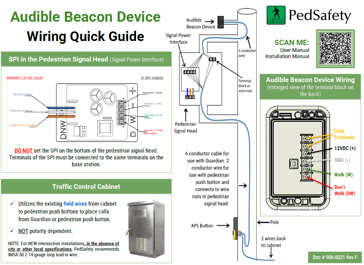
Audible Beacon Device Terminal Connections
The ABD terminal block provides the following field connections:
Terminal | Function |
12VDC | Power input |
GND | Ground reference |
W | Walk signal input |
DW | Don't Walk signal input |
All terminals must match the corresponding outputs on the Signal Power Interface.
Incorrect terminal mapping may prevent proper device operation.
Signal Power Interface (SPI)
The Signal Power Interface is mounted inside the pedestrian signal head and provides the electrical interface between the pedestrian signal indications and the ABD.
Typical SPI connections include:
- Pedestrian signal inputs from the signal head
- Power supply output to the Audible Beacon Device
- Walk and Don't Walk signal outputs
The SPI converts pedestrian signal indications into the appropriate outputs required by the ABD.
Mounting Location
The Audible Beacon Device should be installed near the destination end of the crosswalk to assist pedestrians in locating the crossing endpoint.
Common mounting locations include:
- Signal pole above the pedestrian push button
- Pedestrian signal assembly
- Dedicated mounting bracket near the crosswalk
The device should be positioned so that the audible output is directed toward pedestrians approaching the crossing.
Installation Best Practices
When installing the Audible Beacon Device, follow these recommended practices:
- Ensure wiring connections are secure and properly terminated
- Confirm that Walk and Don't Walk signals are correctly connected
- Route field wiring through approved conduit or pole pathways
- Protect wiring connections using terminal blocks or wire nuts where required
- Verify that the Signal Power Interface is securely mounted inside the signal housing
Commissioning Procedure
After installation is complete, verify proper operation of the system.
- Apply power to the system.
- Confirm that the Audible Beacon Device powers on.
- Trigger a pedestrian call using the push button.
- Verify that audible indications activate during the Walk interval.
- Confirm locator tones or messages operate as configured.
- Verify audio volume and clarity at the crossing location.
If the device does not operate correctly, verify wiring connections and SPI terminal mapping.
Installation Checklist
Before leaving the site, confirm the following:
- Audible Beacon Device is securely mounted
- Signal Power Interface is properly installed inside the signal head
- Terminal connections match SPI outputs
- Wiring is protected and properly routed
- Audible signals activate during pedestrian phases
- Audio output is clearly audible from the pedestrian waiting area
Operating Environment
The Audible Beacon Device is designed for outdoor traffic signal installations.
Operating Temperature Range
- −34°C to +74°C
- −30°F to +165°F
The enclosure is designed to withstand environmental exposure typical of roadside traffic control equipment installations.
When installed correctly, the Audible Beacon Device provides clear audible guidance that improves accessibility and pedestrian safety at signalized crossings.
Was this helpful?
Guardian Duo Installation Guide