Table of Contents
- Maintenance Guide: Value Radar Speed Signs
- Section 1 — LED Status Indicators
- Section 2 — Entering and Exiting Standby Mode
- Section 3 — Power Requirements & Low-Voltage Behavior
- Section 4 — Voltage Testing Locations
- Section 5 — Solar Panel Charging System
- Section 6 — Common Troubleshooting Scenarios
- Section 7 — Wiring Reference
- Section 8 — Remote Control Setup
Maintenance Guide: Value Radar Speed Signs
Value SE speed sign maintenance: LED diagnostics, voltage management, solar charging, and remote control troubleshooting.

- Maintenance Guide: Value Radar Speed Signs
- Section 1 — LED Status Indicators
- Section 2 — Entering and Exiting Standby Mode
- Section 3 — Power Requirements & Low-Voltage Behavior
- Section 4 — Voltage Testing Locations
- Section 5 — Solar Panel Charging System
- Section 6 — Common Troubleshooting Scenarios
- Section 7 — Wiring Reference
- Section 8 — Remote Control Setup
Maintenance Guide: Value Radar Speed Signs

There is a -M at the end of the model number for MUTCD compliant rings
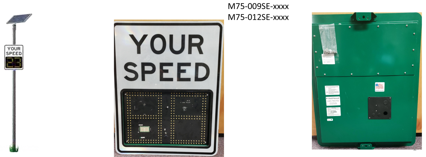
Models Covered:
- M75-009SE-xxxx
- M75-012SE-xxxx
This guide provides troubleshooting, voltage testing, LED indicator behavior, solar/battery diagnostics, and wiring reference information for Value SE radar speed signs.
Section 1 — LED Status Indicators
The sign includes 5 LED diagnostic indicators located on the front display board. These LEDs are used to determine operating state, standby mode, low-power conditions, and remote-control status.
LED #5 — System Status LED
This is the lowest LED on the 5-LED vertical indicator row.
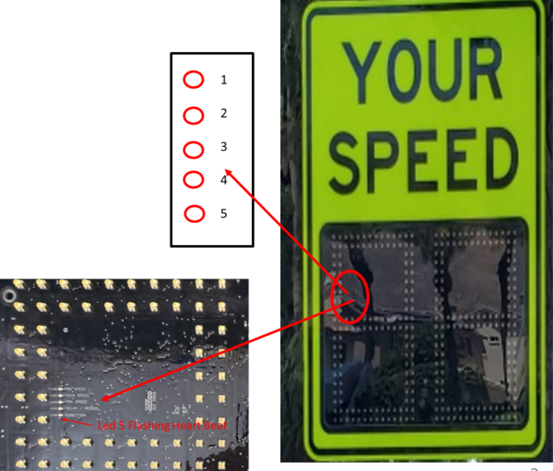
LED5 Behavior & Meaning
- OFF → No power / very low power
- Blink every 15 seconds → Standby Mode (STDBY)
- Sign will NOT detect traffic
- Sign will NOT display speeds
- Blink every 1 second → Normal Operation
- Sign is ON
- System will respond to traffic
If LED5 is ON or blinking once per second, the sign is functioning and can continue normal setup.
Section 2 — Entering and Exiting Standby Mode
If LED5 blinks every 10–15 seconds, the sign is in STDBY mode.
The sign enters standby for two reasons:
1. User-Initiated via Remote
Someone used the remote and placed the sign into standby.
Fix:
- Open remote
- Press and hold Setup until the LED stays lit
- Press Sign
- Enter 1221
- Remote will exit standby
2. Low Voltage Event (< 11.8V)
The sign will automatically enter STDBY when voltage is too low to operate.
The sign will not exit STDBY until voltage has recovered.
Section 3 — Power Requirements & Low-Voltage Behavior
Value SE signs require 12.5V or greater to fully recover from low-voltage states.
Voltage Levels & Symptoms
Supplied Voltage | Behavior / Symptoms |
12.25V | Display brightness will dim (ex: 16 → 12) |
12.00V | Display dims further; lowest speed threshold increases; squelch increases |
11.80V | Squelch increases to reduce detection range; brightness drops further |
11.70V | Sign enters power-down mode; LED5 blinks every ~10s |
11.20V | Sign enters Sleep Mode; LED does NOT blink; sign unresponsive; all schedules canceled |
Voltage Recovery
Recovery Voltage | Behavior |
11.8V rising | Wake-up stage; sign still unreliable; remote/menu available but sign not fully recovered |
12.5V+ | Full recovery. All values restored. |
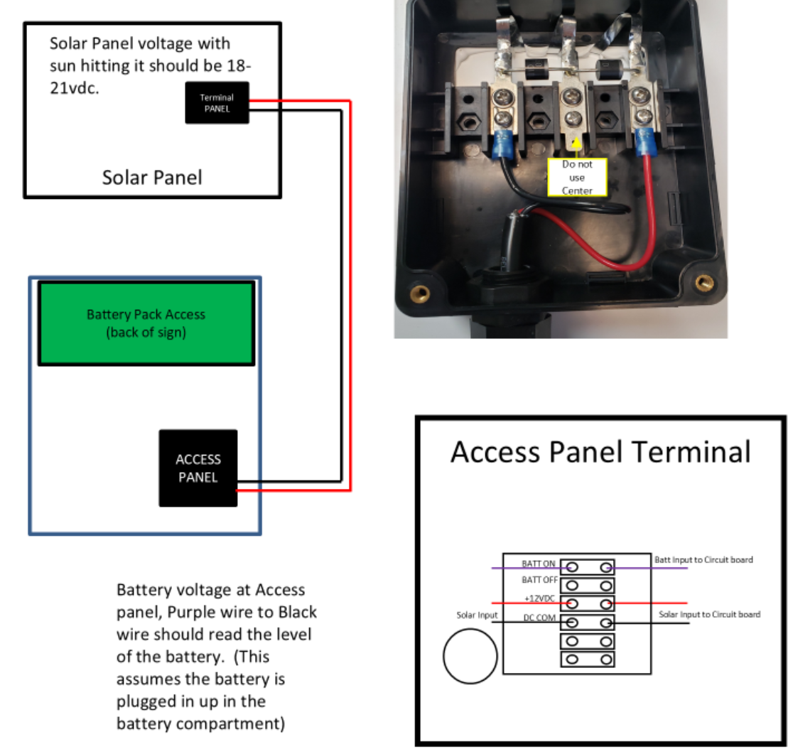
Section 4 — Voltage Testing Locations
There are three places to check voltage:
- Battery Pack
- Terminal Block inside Access Panel
- Solar Panel Access Panel
Battery Voltage Expectations
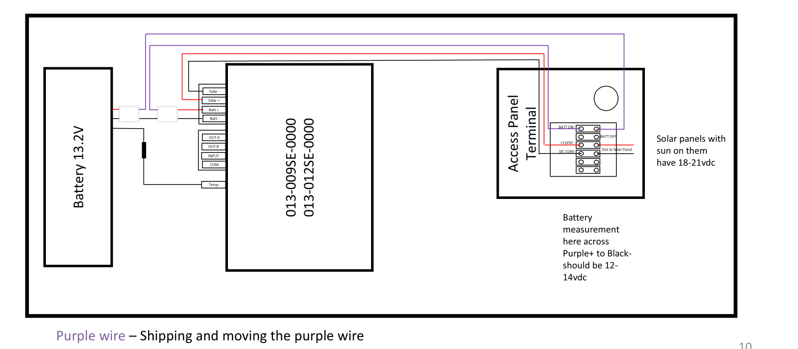
- Should read 12–14.5V depending on charge state.
- Purple wire to black wire inside the access panel reflects battery level.
- Testing directly at the battery pack requires opening the pack and placing meter leads on the connector.

If voltage at the access panel is ≥ 12.8V and wiring is correct, the sign should operate normally.
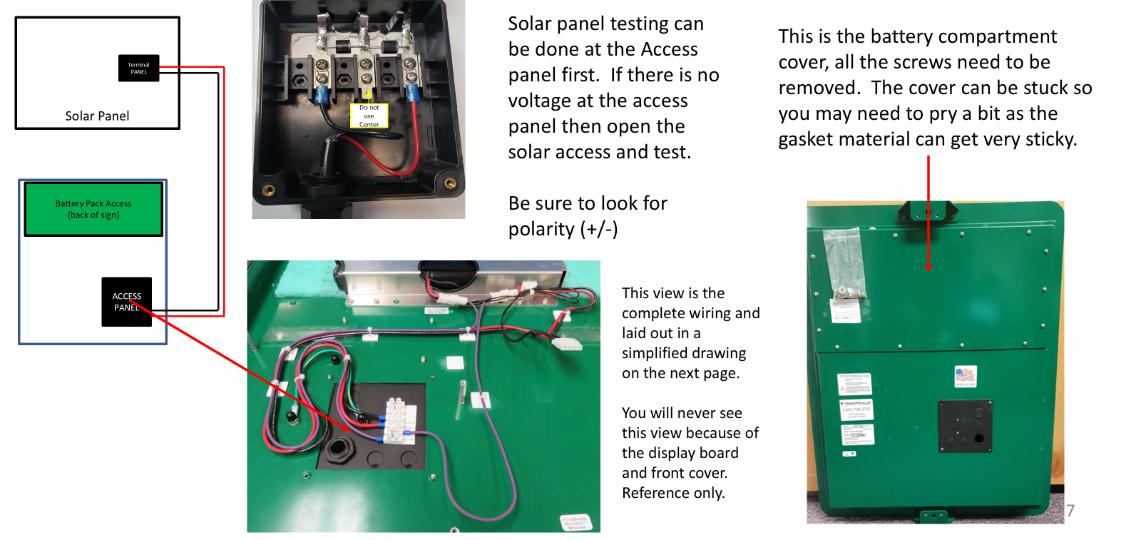
Section 5 — Solar Panel Charging System
Normal Solar Panel Output
- 18–21VDC in full sun
- Measured at solar access panel OR sign access terminal block
MPPT Charging Behavior
- Below 13.4V battery → charger activates
- Above 13.4V → system regulates between 14.3–14.7V for optimized battery life
Why Battery Voltage Might Be Low
- Solar Panel Issue
- 8V or less indicates wiring damage or panel failure
- Check solar access panel
- Battery Pack Failure
- Charge Circuit Issue
Section 6 — Common Troubleshooting Scenarios
1. Sign Has No Power or LEDs
Check in this order:
- Solar panel polarity & connection
- Purple wire alignment (misalignment = battery unplugged)
- Solar voltage 17–23V and battery voltage 12.5–14.5V
If solar and battery are good but LEDs remain off → control board likely failed.
2. Sign Only Blinks LED #1 (top LED)
This indicates:
- Battery is disconnected
- Sign is attempting to run on solar only
- Solar output is insufficient to power system under load
Fix:
Check purple wire → verify battery voltage.
3. Sign Enters Standby Repeatedly
- Open access panel
- Verify purple wire alignment
- Measure battery voltage
- Measure solar input (red lead on solar+, black on solar–)
4. Sign Does Not Display Speed
Possible causes:
- Radar squelch setting too high
- Display failure
- Low voltage recovery incomplete
Fix:
- Use remote
- Try navigating menus
- Ensure squelch = 20
- If menus display but speed does not → display board likely failed
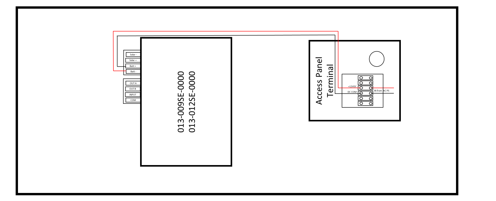
Section 7 — Wiring Reference
Your sign wiring includes the following key components:
- Battery 13.2V Module
- 013-009SE / 013-012SE Display Boards
- Access Panel Terminal Block
- Battery ON/OFF
- Solar Input
- DC Common
- Purple Alignment Wire
- MUST be aligned for the sign to power from battery
- Misalignment = battery disconnected
Section 8 — Remote Control Setup
Basic Remote Functions
Setup Procedure
- Hold Setup until LED stays lit
- Press Sign
- Enter 1221

- LED goes out → remote paired and ready
Remote Emulator
An online simulator is available for training techs on LED indicators and menus. (Link to simulator)
Any button press illuminates the remote’s LED indicator.
Was this helpful?
Value sign VIDEO LINK M75-009SE or 012SE-00xx Intall - Setup- Remote use