Table of Contents
Illuminator wiring and configuration M75-SA314-0000
Trafficalm crosswalk illuminator: nighttime light with careful wiring, config based on push button type

There is a -M at the end of the model number for MUTCD compliant rings
The Trafficalm M75-SA314-ILSSR-000 Illuminator is a white light that shines on the crosswalk during nighttime operations. The white illuminator is designed to work only at night. Be sure to find the testing options after completing the wiring and configuration.
The wiring and configuration is dependent on the type of push button being utilized for the installation.
3 most common button types are:
Standard- This would be a simple 2 wire button.
Audible Talking Buttons: PedSafety Guardian
Polara INX
What is in the box: 1. Illuminator
2. Wiring harness 042-ILSSR-0000 (NOTE: the pictured electronic tray is not in the box, its in the Controller or Collaborator.)
INSTALLATION:
CAUTION: Use extreme caution when disconnecting and reconnecting the battery wires. Do not allow the exposed wires to touch each other or short out on anything.
Installation wiring harness note: Your illuminator comes with an extra wiring harness. This harness is only used with the Audible Talking Buttons. If using a standard 2 wire button follow these instructions.
Installation for a STANDARD 2 wired push button wiring:
After mounting the illuminator light and routing the wires into the control box.
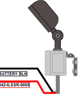
1.Connect the RED+ to the RADAR port and the Black- to the RADAR port as shown.2.In the software SETUP you will choose DEVICE TYPE: ILLUMINATOR.
Configuration is done in the Controller setup: In the software SETUP you will choose DEVICE TYPE: ILLUMINATOR.
Installation when using an Audible Talking Button
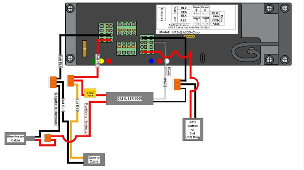
PEDSAFTEY GUARDIAN Wiring: You will need the extra Wiring harness 042-ILSSR-0000 that came with the illuminator
Illuminator harness installation
- After mounting the illuminator light and routing the wires into the control box.
- Unplug the BATT/Solar connector
- Unplug the RADAR connector
- Using the ILSSR cable harness, plug in the connector with the BLACK, WHITE and RED wires into the RADAR PORT.
- Using the ILSSR cable harness, plug the connector with the Black and RED wires into the Batt/Solar port.
- Remove 1 at a time the Batt/Solar wires from the old removed connector. Both solar wires will go into the new connector RED+. BLACK-. The RED+ Batt wire will be connected to the Orange WAGO connector with the other RED wires. The Batt- BLACK wire will be connected to the Orange WAGO connector.
- The illuminator wires will be connected to the new harness. RED+ will connect to the 2 slot Orange WAGO and the BLACK- will connect to the 3 slot Orange WAGO with the BATT-.
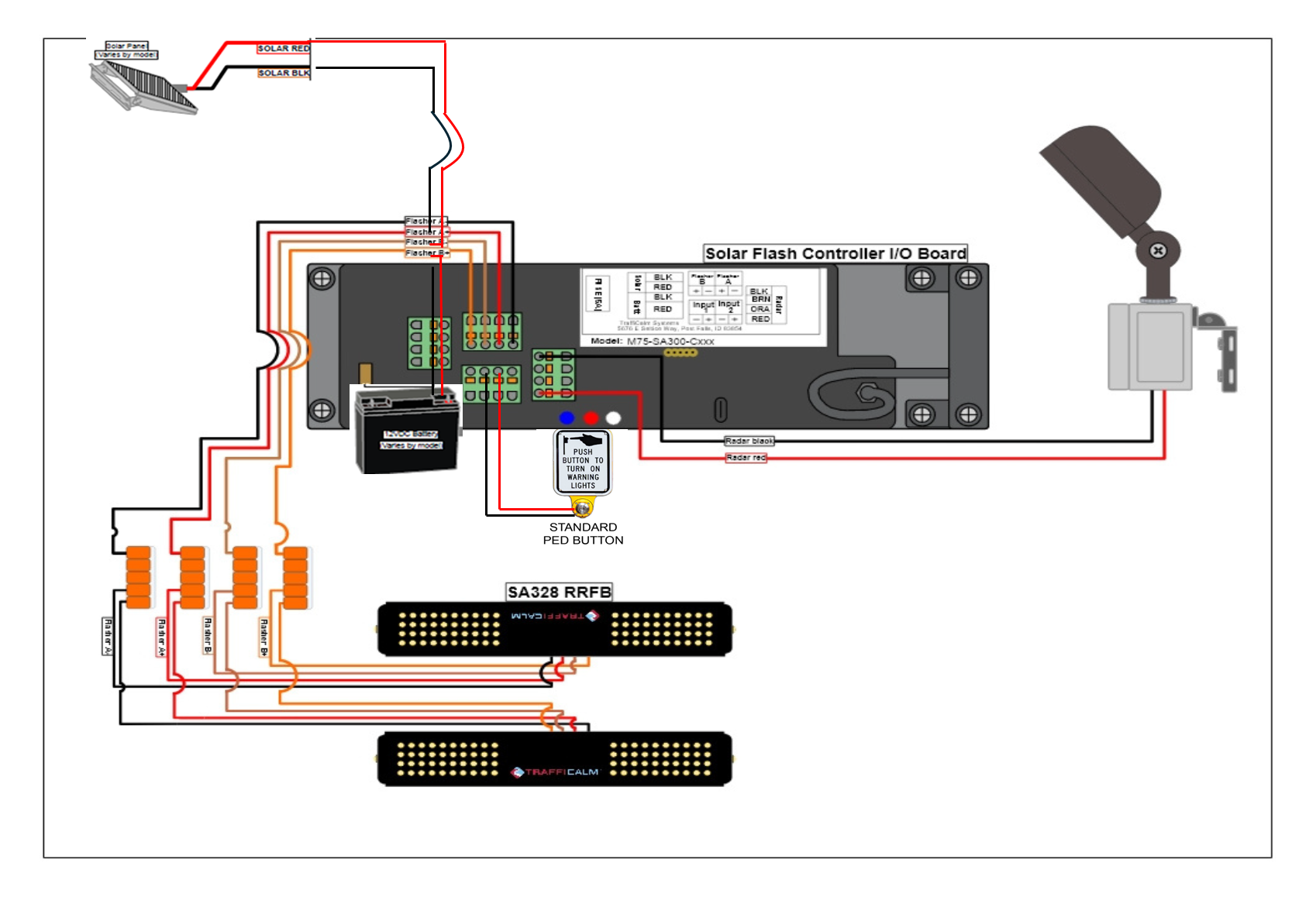
- Follow wiring diagram for Buttons, RRFBs or any LED rings
Configuration is done in the Controller setup: In the software SETUP you will choose Audilble Talking Button
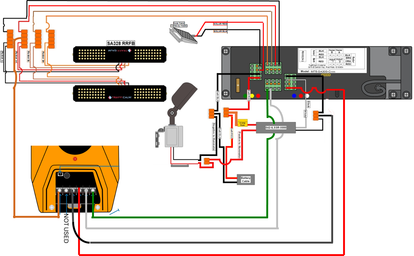
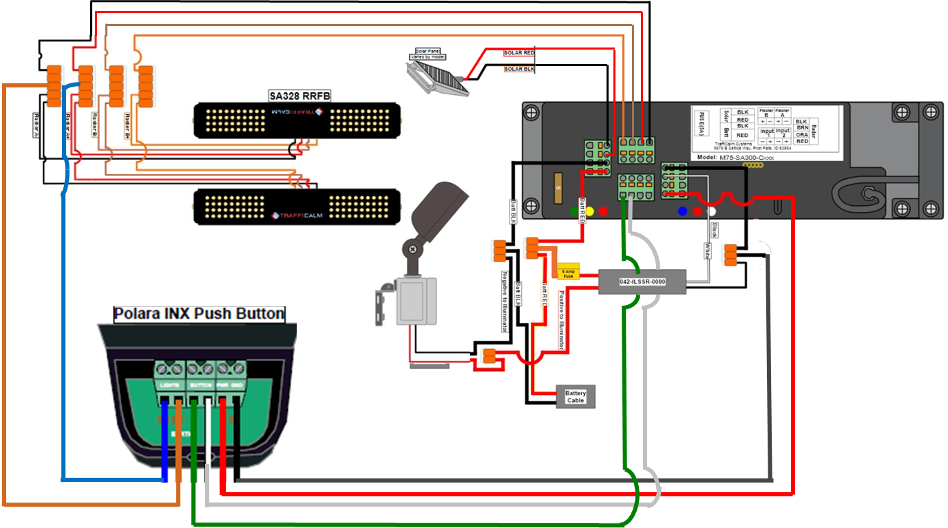
Polara INX wiring: You will need the extra Wiring harness 042-ILSSR-0000 that came with the illuminator.
- After mounting the illuminator light and routing the wires into the control box.
- Unplug the BATT/Solar connector
- Unplug the RADAR connector
- Using the ILSSR cable harness, plug in the connector with the BLACK, WHITE and RED wires into the RADAR PORT.
- Using the ILSSR cable harness, plug the connector with the Black and RED wires into the Batt/Solar port.
- Remove 1 at a time the Batt/Solar wires from the old removed connector. Both solar wires will go into the new connector RED+. BLACK-. The RED+ Batt wire will be connected to the Orange WAGO connector with the other RED wires. The Batt- BLACK wire will be connected to the Orange WAGO connector.
- The illuminator wires will be connected to the new harness. RED+ will connect to the 2 slot Orange WAGO and the BLACK- will connect to the 3 slot Orange WAGO with the BATT-.
- Follow wiring diagram for Buttons, RRFBs or any LED rings.
Configuration is done in the Controller setup: In the software SETUP you will choose Audilble Talking Button
TESTING after wired in and configuration is setup properly for the button type used.
The white illuminator will only work at night. You can wait for nighttime, or use one of two options to simulate nighttime, then just press the crossing button.
Option 1: Remove 1 wire either red or black wire from the solar panel. This can be done at the control board connector or solar panel Jbox.
Option 2: Place a jacket or blanket over solar panel to block the sun.
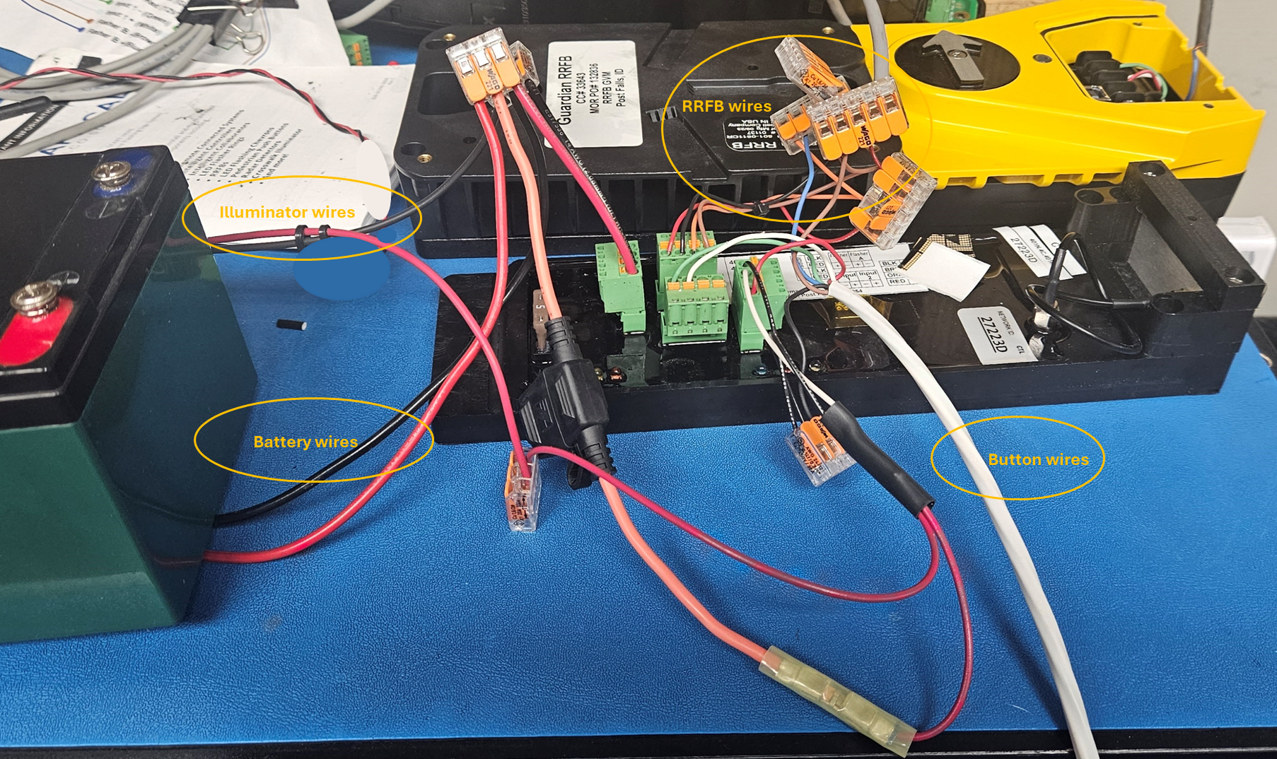
Picture example of a PEDSAFETY Guardian wired up.
Was this helpful?
Push 2 cross Wiring Diagrams
Chevron Curve Warning Setup Guide